
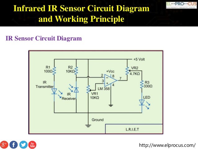
Infrared IR Sensor Circuit Diagram and Working Principle The first IR circuit will just show how the pair (IR LED & Photodiode) works. By using a transistor, we can arbitrarily amplify the analogue signal from the photodiode to power the LED. The circuit is very simple, all it needs is: Resistor: 2x 220ohm (or similar), 1x 10k. Diode: 1x IR LED, 1x Generic LED, 1x Photodiode
This project demonstrates how to create a basic circuit using an IR sensor, buzzer, and LiPo battery, with no Arduino involved. The IR sensor triggers the bu

How to make simple Infrared Sensor Modules Circuit Diagram
How to make proximity sensor. Simple IR Proximity Sensor Circuit. Diy IR Sensor ..Welcome to our channel "PendTech"I'm .Puspendu Ghosh🔘 ABOUT THIS VIDEO
// Simple Proximity Sensor using Infrared // Description: Measure the distance to an obstacle using infrared light emitted by IR LED and // read the value with a IR photodiode. The accuracy is not perfect, but works great // with minor projects. // Author: Ricardo Ouvina // Date: 01/10/2012 // Version: 1.0 In this video, we learn how to build a simple infrared sensor circuit that can detect the obstacles. This is a tutorial series on how to build electronic cir

The Simplest IR Sensor Circuit without Arduino Circuit Diagram
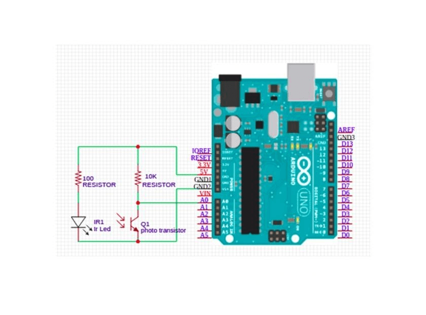
Here you can find a wide variety of IR phototransistors at Jameco.. The circuit we will build from these parts is: IR Detector Circuit. This circuit is very simple. When the IR phototransistor isn't exposed to any infrared light, there can be no current flow through the transistor, because infrared light is what produces base current in the transistor.
