dc Converter Circuit Diagram Introduction: AC to DC Converter The full-wave rectifier consists of an arrangement of diodes, capacitor, resistor, and an AC voltage source. The input to the circuit is an AC voltage source and its output is a DC signal, the output is not purely DC but with the use of a smoothing capacitor the output voltage can become relatively stable.

Divide the AC voltage by the square root of 2 to find the DC voltage. Since an AC power supply sends voltage in alternating waves, DC voltage will be lower once you convert it. Write out the formula V AC /√(2) and replace V AC with the AC voltage you found with your multimeter. Learn how an AC to DC converter, also known as a rectifier, works and what components it consists of. See the block diagram and the function of each component in converting AC power to DC power.

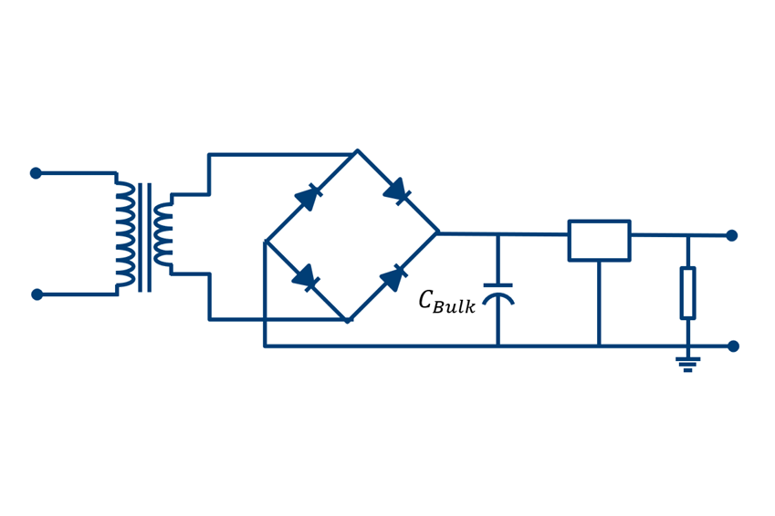
AC to DC Converter Circuit Diagram
Learn how to use four diodes to create a diode bridge rectifier that converts alternating current (AC) into direct current (DC). See the circuit diagram, how it works, and its applications in DC power supplies. Learn how to use a buck converter IC to convert AC to DC power with a non-isolated topology. See the circuit diagram, components, and calculations for this project.

The only way to do that is by using AC current, which switches between positive and negative voltages at 50-60Hz. In order for electronic circuits to work, we must convert this stepped-down AC voltage to a flat, stable DC voltage. That's where the bridge rectifier comes in, and in this case a full-wave rectifier.

How to Convert AC to DC: 11 Steps (with Pictures) Circuit Diagram
Learn how to build an AC to DC converter circuit using a transformer, diodes, capacitor and LDO. See the schematic, working, limitations and video of this project.